Saturday, July 21, 2012

Study of DC series motor


OBJECTIVES: 
 1. Study the performance characteristics of a DC series motor.
 2. Get familiarized with the components involved.

 APPARATUS:  Dismantled DC machine
                                   DC series motor
                                  Ammeter 0-30A
                                  Voltmeter 0-300V
                                  Rheostat 20A/6Ω
                                  Tachometer
                                  Absorption Dynamo meter

PROCEDURE:

The machine was examined and the terminals were identified. Then the circuit was connected with the rheostat, ammeter and the dc series motor connected in series. Then the selected voltmeter was connected in parallel to the dc series motor. The whole system was then supplied with a 220V dc supply.
Then the motor was started with a sufficient load on the pan. The values of the load (W), spring load (w), voltage (V), armature current (A) and the speed of the motor (Nr) were noted down. Then the load on the pan was decreased in suitable amounts and the above quantities were noted down at these different loads.
In order to avoid excessive heating the readings were taken as fast as possible and once they were taken the machine was switched off and motor wheel was cooled with water in order to avoid damage to the machine.
Thereafter, the resistance of the armature and field winding was taken down. Further thereafter the circumference value of the motor wheel was measured and noted down.

THEORY:

Direct current (DC) motors operate on a magnetic field produced by the field winding in the stator (stationary part of the motor) interacting with the field produced by the armature winding in the rotor (rotating part). The basic constructional features of a typical two pole DC motor and the circuit model are shown in the figure.
The field is produced by direct current in field coils or by permanent magnets on the stator. The output, or armature, windings are placed in slots in the cylindrical iron rotor. In a direct-current generator—a simplified machine with only one rotor coil—the rotor is fitted with a mechanical rotating switch, or commutator, that connects the rotor coil to the stationary output terminals. This commutator reverses the connections at the two instants in each rotation when the rate of change of flux in the coil is zero, i.e.  when the enclosed flux is maximum (positive) or minimum (negative). The output voltage is then unidirectional but is pulsating for the single case of one rotor coil. In practical machines, the rotor contains many coils symmetrically arranged in slots around the periphery and all connected in series. Each coil is connected to a segment on a multi-bar commutator. In this way, the output voltage consists of the sum of the induced voltages.
The DC motors needs slip rings or split rings (commutator) on the rotor shaft and a set of brushes positioned over them to supply the armature winding. DC motors can be categorized into four basic types depending on the method used for connecting the winding.  

CALCULATIONS:

The first set of reading of the observed values are used below to calculate the Electrical Input, Torque, Mechanical Output, Efficiency, Copper loss, Mechanical loss.

W (weight)         = 50 x 0.4536
                                    = 22.68 kg

w (weight)          = 5  x 0.4536
                                    = 2.27 kg

            Radius (r)             = circumference/ 2л
                                    = 0.72 x 7/44
                                    = 0.1146m

Speed (rad s-1)             = 2 x л x Nr/60
                                    = 2 x л x 1400/60
                                                = 146.6 rad/s

Electrical Input = V x I
                                                = 200 x 19.2
                                                = 3840 W

Torque                 = (W-w) x g x r
                                    = (22.68 – 2.27) x 9.8 x 0.1146
                                    = 22.92 Nm.


Mechanical Output     = τ x ω
= 22.92 x 146.6
= 3600.0 W

Efficiency                   = Mech. Output / Elec. Input
=3600.0 /3840
= 87.5 %

Copper loss                 = I2R
= 19.22 x (0.6+1.4)
= 737.26 W

Mechanical loss           = Electrical Input – Mechanical output – Copper loss
= 3840 – 3600.0 – 737.26
= - 497.28 W             

RESULTS:

Set
Angular
Velocity
(rad/s)

Electrical
Input
(W)
Torque
(Nm)
Mechanical
Output
(W)
Efficiency
(%)
Copper loss
(W)
Mechanical
Loss
(W)
1
146.6
3840
22.92
3600.0
87.5
737.26
- 497.28
2
150.77
3760
21.90
3301.8
87.8
706.88
-248.68
3
152.86
3720
21.39
3269.7
87.8
691.92
-241.62
4
154.96
3640
20.38
3158.1
86.7
662.48
-180.58
5
157.05
3560
18.34
2880.3
80.9
633.68
46.02
6
159.15
3480
16.81
2675.3
76.7
605.52
199.18
7
165.42
3280
15.28
2527.6
77.0
537.92
214.48
8
173.80
3160
13.25
2302.9
72.8
499.28
319.18


DISCUSSION:

Direct current (DC) motors operate on a magnetic field produced by the field winding in the stator (stationary part of the motor) interacting with the field produced by the armature winding in the rotor (rotating part). The field is produced by direct current in field coils or by permanent magnets on the stator. The output, or armature, windings are placed in slots in the cylindrical iron rotor. In a direct-current generator—a simplified machine with only one rotor coil—the rotor is fitted with a mechanical rotating switch, or commutator, that connects the rotor coil to the stationary output terminals. This commutator reverses the connections at the two instants in each rotation when the rate of change of flux in the coil is zero—i.e., when the enclosed flux is maximum (positive) or minimum (negative). The output voltage is then unidirectional but is pulsating for the single case of one rotor coil. In practical machines, the rotor contains many coils symmetrically arranged in slots around the periphery and all connected in series. Each coil is connected to a segment on a multi-bar commutator. In this way, the output voltage consists of the sum of the induced voltages.The DC motors needs slip rings or split rings (commutator) on the rotor shaft and a set of brushes positioned over them to supply the armature winding.
A series wound DC motor normally drives loads that require high torque and do not require precise speed regulation. Series DC motors are ideal for traction work where the load requires a high breakaway torque. Such uses include locomotives, hoists, cranes, automobile starters, or oil drilling rig applications. An increase in load results in an increase in both armature and field current. As a result, torque increases by the square of a current increase. Speed regulation in series motors is inherently less precise than in shunt motors. If motor load diminishes, current flowing in both the armature field circuits reduces as well. This results in a greater increase in speed than in shunt motors. Removal of mechanical load from series motors results in an indefinite speed increase which can destroy the motor or bearings. Small series motors usually have enough internal friction to prevent high-speed breakdown, but larger motors require to be controlled.
                Components of a series motor include the armature and the field. The same current is impressed upon the armature and the series field.  The coils in the series field are made of a few turns of large gauge wire, to facilitate large current flow. This provides high starting torque, approximately 2 ¼ times the rated load torque. Series motor armatures are usually lap wound. Lap windings are good for high current, low voltage applications because they have additional parallel paths for current flow. Series motors have very poor speed control, running slowly with heavy loads and quickly with light loads. A series motor should never drive machines with a belt. If the belt breaks, the load would be removed and cause the motor to over speed and destroy itself in a matter of seconds. Common uses of the series motor include crane hoists, where large heavy loads will be raised and lowered and bridge and trolley drives on large overhead cranes. The series motor provides the starting torque required for moving large loads. Traction motors used to drive trains are series motors that provide the required torque and horsepower to get massive amounts of weight moving.  On the coldest days of winter the series motor that starts your car overcomes the extreme cold temperatures and thick lubricant to get your car going.
The shunt motor is probably the most common dc motor used in industry today. Components of the shunt motor are the armature and the field. The coils in the shunt field are composed of many turns of small wire, resulting in low shunt field current and moderate armature current. This motor provides starting torque that varies with the load applied and good speed regulation by controlling the shunt field voltage. If the shunt motor loses its field it will accelerate slightly until EMF rises to a value sufficient to shut off the torque producing current.  In other words, the shunt motor will not destroy itself if it loses its field, but it won’t have the torque required to do the job it was designed for. Some of the common uses of the shunt motor are machine shop lathes, and industry process lines where speed and tension control are critical.
When comparing the advantages of the series and shunt motors, the series motor has greater torque capabilities while the shunt motor has more constant and controllable speed over various loads. These two desirable characteristics can be found in the same motor by placing both a series field and shunt field winding on the same pole. Thus, we have the compound motor. The compound motor responds better to heavy load changes than a shunt motor because of the increased current through the series field coils.  This boosts the field strength, providing added torque and speed. If a shunt coil is added to a series motor at light loads (when a series motor tends to over speed) the added shunt field flux limits the top speed, eliminating self-destruction. Common uses of the compound motor include elevators, air compressors, conveyors, presses and shears. Compound motors can be operated as shunt motors by disconnecting the series field. Many manufacturing process lines are designed this way. The reason being that, most off the shelf motors are compound motors, and the series field can always be connected later to provide additional torque, if needed. Compound motors can be connected two ways, cumulatively and differentially. When connected cumulatively, the series field is connected to aid the shunt field, providing faster response than a straight shunt motor. When connected differentially, the series field opposes the shunt field.  
Differentially connected compound motors are sometimes referred to as “suicide motors,” because of their ability for self-destruction.  If perhaps, the shunt field circuit were to suddenly open during loading, the series field would then assume control and the polarity of all fields would reverse. This results in the motor stopping, and then restarting in the opposite direction. It then operates as an unloaded series motor and will destroy itself. Differentially connected motors can also start in the opposite direction if the load is too heavy. Therefore, it is seldom used in industry.

Applications of motors
1.Shunt excited dc motors
These have fairly constant speeds against a varying load or torque. Therefore applications include situations where a constant speed is required.
E.g. Lathes, Conveyors, Fans, Machine tool drives

2. Series excited dc motors
These are able to create large torques at low speeds (high starring torque) it can be used to accelerate very heavy loads from stand still.
E.g. Driving cranes, Driving electric locomotives, Steel rolling mills

3. Compound excited dc motors
These have Combine characteristics of both shunt and series wound motors. The series winding gives good starting torque and shunt winding ensures a comparatively constant speed.
E.g. Planers, Shears, Guillotines, Printer machines, Power presses which needs peak loads at certain   
                                                                                                                                                                                                instances

4. Separately excited dc motors
These are used in applications where an independent armature control and a field control are required.
E.g.  Steel and Aluminum rolling mills, Controls motors

5. Permanent magnet motors
These are used for low power applications.
E.g. Automobiles, Starter motors, Wiper motors, Lowering windows, Toys, Electric tooth brushes

REFERENCE:
                                Machine Elements in Mechanical Design by Robert L. Mott.
                                Electric Machines by I.J. Nagrath and D.P.Kothari


Sunday, June 24, 2012

Perkins Diesel Engine


Introduction


          Rudolf Diesel a German engineer was the person who has introduced the Diesel engine in 1890s.
 at that time   they used coal as fuel and this invention had done great revolution in mechanical scheme.
After 7 years he  invented a compression ignition engine which is run in kerosene.

          These engines are very effective and low cost in inner operation. Consume less fuel. So these
types of engines were very popular in that time. At that time and now also they are being use in big and
 heavyequipmentshipping and railways. In these days most heavy duty busses, trucks, trains and autom
obiles also get poweusing these types of engines.

          Most commonly Diesel engines produce energy and heat by air compression ignition in fuel insid
 the cylinder. (Internal combustion engine).When the fuel (Diesel) coming in side of the cylinder there
 exists hot air and that air have enough heat to burn the fuel. Therefore it does not need spark plugs. It is
a very much advantage.Diesel  engines burn petroleum products like kerosene, jet fuels etc.

          Inside a diesel engine also there are cylinders and pistons. When the piston moves up and down
 inside the cylinder   the connecting rod which is connected to the piston is transmitting power to crank
shaft to rotate it.This is the basic operation inside the engine.

          Diesel engines are combust the fuel air mixture by compression. Therefore it should apply higher
load to the pistons and cylinders. So the inner and outer components should be having great strength to
withstand this much of higher forces and pressure. Due to these components are very strong the cost to
 make them also is high. Therefore the cost   of the engine is also very high.

Perkins engine is a 4 cylinder, 4 stroke diesel engine, that means the internal combustion happens in four strokes in side the cylinder


          Here is the brief introduction about four strokes in Perkins diesel engine.

·    Intake stroke: - In this stroke cylinder sucks air by opening the inlet valve. In this stroke piston is
          in Bottom Dead Center.

·    Compression stroke: – In here intake valve closed and piston moves up to the cylinder. Within this
                                                strok air will compress highly and reached high temperature. At the
                                                finishing of this stroke fuel will be injected.

·   Combustion stroke: – Pressure and temperature will be increased due to the combustion happens.
                                              Therefore piston moves down.

·   Exhaust stroke: – At the beginning of this stroke piston in its bottom position. During this stroke                                           piston coming up and outlet valve will open simultaneously. So the exhaust
                                       gasses can move from the cylinder.


Perkins Diesel Engine


Inside the Four cylinders four stroke Engine With all four strokes..
                                                         
Theory

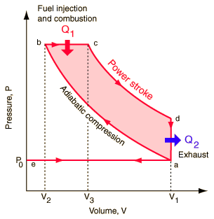
Basic Diesel Cycle


·                Process a-b : Isentropic compression
·                Process b-c:  Reversible constant pressure heating
·                Process c-d : Isentropic expansion
·                Process d-a : Reversible constant volume cooling


By this experiment we are trying to get some knowledge about Perkins diesel engine with its design and operations and the performance in several circumstances such as fuel consumption ,efficiency etc.

Useful Notations;
         
          V         Volume
          T         Temperature
          Q         Heat
          γ          Cp / Cv
          Cp       Specific heat capacity under constant pressure
         Cv        Specific heat capacity under constant volume
          α          Cut-off ratio = V3 / V2
          r           Compression ratio = V1 / V2
U         Internal Energy


                 η= Net work / Work in


According to the 1st law of thermodynamics,

∆U = ∆Q - ∆W
∆U=0, therefore
∆Q = ∆W

Net work  =  net heat =  Q(bc) + Q(da)
Work in  =  heat in  =  Q(bc)

η=Q(bc)  + Q(da) / Q (bc)
η=1 + [Q(da) / Q (bc)]

Q(bc) = Cp (Tc - Tb)
Q(da) = Cv (Ta - Td)


Standard notation

BP                = Brake power
FP                = Friction power
IP                 = Internal power
K (constant) = 4500
W                 = load (lbs)
N                  = Speed (rpm)
SFC              = Specific fuel consumption
BPMF          = Brake power mean efficiency                                                                               
BMEP         = Brake mean effective pressure
h                   = Manometer water head (inch of water)
T                  = temperature at the orifice (K)
H                 = Atmospheric pressure (inch of Hg)
d                  = Orifice diameter
D                 = Cylinder bore
L                 = Stroke
           
BP= W.N/K   (kW)
IP = BP +  FP
BMEP = BP / (Π / 4. D^2. L. (N / 2) (4 / 60) )
Volume inhaled = (4.193 / 35.22) D^2. ( h.T / H) ^ 0.5        (m^3 / min)
Swept volume = 4. (Π / 4 D^2 L). N /2       (m^3 / min)

Performance parameters

SFC = (Fuel consumption / BP). 3600    (kg / kWh)
Mechanical efficiency = BP / IP
Brake thermal efficiency = overall efficiency = BP / Rate of heat input by the fuel
Volumetric efficiency = volume inhaled / Swept volume
Indicated thermal efficiency = IP / Rate of heat input

  Calculation of frictional power

          This can be observed from the graph of fuel consumption vs. brake power. We have to get thefuel consumption in zero power, because when frictional power will be available only when the brake power is zero in the engine. So the frictional power will equal to internal power.

                                  Internal power = Frictional power + Brake power
                                  Brake power = 0
                                  Therefore,
                                  Internal power = Frictional power

                      Frictional power = (Fuel consumption where the brake power is zero) * Calorific value  

  Heat balance

                      Rate of heat          =    internal   +  Rate of heat rejection  +  Rate of heat rejection
                      input by the fuel          power              by the water                  by the exhaust gas


 Procedure

1.              Open the inlet water supply valve fully and the outlet valve slightly of the dynamometer.
a.                                      i.e. Dynamometer: Instruments measuring energy expended.

2.              Make sure all the valves in the piping between the source of the water supply and the dynamometer inlet are fully open.
3.              The engine may now be started.
4.              Loads may be regulated by opening the sluice gates by means of the hand-wheel and simultaneously operating the engine throttle, until the desired load and speed are obtained.
5.              Adjust the outlet valve to pass sufficient water to keep the temperature at a reasonable figure.
6.              A hand wheel is provided on top of the balance frame to adjust the height of the balance arm. Make sure that this wheel is always set to the horizontal position when taking B.HP readings.


Equipment

·                Perkins diesel engine.
·                4 cylinder 4 stroke engine
·                coolant  :- water cooled
·                Engine is coupled with a Henan-Froude water cooled dynamometer, So the torque,  speed in rpm,
·                 can be measured.
·                Measuring air mass flow rate: - an orifice plate fitted to an air reservoir                                                                                                          this is attached to the inlet manifold of the engine.
·                Measuring pressure across the orifice: - Using an inclined water manometer.


Engine parameters

·                Orifice diameter        = 2.05 inches
·                Length of the stroke  = 3.05 inches
·                Cylinder bore            = 3 inches
·                Speed of rotation       = 1500 rpm


Fuel parameters

·                Specific heat capacity of the fuel   = 1.08kg / kJ.K
·                Density of the fuel                          = 880 kg /m^3
·                Calorific value of fuel                     = 44290 kJ/kg


 Discussion

     Perkins engine is a diesel engine which is working according to the diesel cycle. Because of these
advantages of the diesel cycle we can convert this Perkins engine to be very effective engine which
having more efficiency, high fuel consumption, smoothness etc. we can enhance high performances
 using Perkins engine than gasoline or other fuel engines by internal combustion.

          There were many differences between traditional gasoline engine and Perkins engine. We can categorize this are basic two categories.


·                Ignition method
                      Gasoline :- Spark Ignition
                      Diesel :- Compression Ignition

·                Fuel Injection
                      Gasoline :- port fuel injection.
                      Diesel :- Direct fuel injection.


 Advantages and Disadvantages of Perkins Diesel Engine.


Advantages:-


·         This engine has high expansion ratio and reached high temperature in combustion. Due to these       reasons Diesel engine has mare efficiency and greater fuel efficiency than other engines. Gasoline engines basically having 20-25% efficiency while Diesel engines have efficiency more than 30%.

·         They are no high powered electrical ignition system to burn fuel. So it is not more harmful to environment because there are no use of carbon coils, wires, unwanted metals and also it eliminates a source of radio frequency emissions which are connect with communication and navigation.

·         For a given load to the engine, Diesel engine remains its efficiency constant while at that load gasoline engine reduces its efficiency to put more output powers.

·         Life time of the Diesel engine is approximately twice a gasoline engine Due to the diesel engine are made by high strength metal parts than traditional gasoline engines.

·         Can deliver the generated power continuously than the gasoline engine.

·         High compression ratio. Volume of the cylinder when the piston at BDC to the volume of the cylinder when the piston at the TDC.
  • When higher Compression ratios,
·         The temperature of air is higher at the end of the compression stroke,
·         Having higher thermal efficiency,
·         Greater fuel economics,
·         Generate high temperatures required for auto ignition.

·         Also Diesel engines actually the fuel diesel is more safer than other fuel like petrol. Though diesel get fired in normal air with the support of some fire pulse, it does not explore in severe manner like petrol. It would be great advantage for the industry.

·         And the law vapor pressure of diesel gives more advantage for marine applications. So the fuel air       mixtures which is accumulation of explosive is extremely hazard and for while diesel engines are immune to vapor locking.

·         Compression Ratio of Diesel Engine to Gasoline Engine
  • Spark ignition compression ratio         8:1 to 12:1
  • Compression ignition ratio      14:1 to 25:1


·         Compression ratio of Diesel engine
  • The Compression ratio indicates that in how much of strength the cylinder can compromise it’s contain to outside. As the figure indicates the engine which is used otto cycle is having a smaller compression ratio than the diesel engine. So the engine can work with high efficiency and it also very important for industrial     and other applications.


Disadvantages:-


·         Main disadvantage is that the Diesel engine emits Carbon Monoxide with its exhaust gas. This affects the surrounding and our environment. But this is very small by comparing the gasoline  engine. Because, gasoline engine emits unburned fuel parts and several other chemical components which are more harmful to surrounding as well as human beans.

·         Another disadvantage is that in this diesel engine fuel injected before power stroke. If there is nit sufficient air to get that fuel so fuel will not burned 100% correctly. So that incomplete combustion make exhaust gas black in color and very thick and this unburned fuel will reaches outer environment and it is not very safer.

·         Other thing is those engines are very expensive than other engine types. Because it cost highly in manufacturing and maintenance. Diesel engines are very echo friendly than other engines and they are having high technology to reduce the various components in exhaust system. So this increases its price than other models.

·         When the engine working it emits high noise. This is called as Diesel knock and this noise caused because the diesel combustion process and sudden ignitions.

·         Diesel engines have long stroke lengths to achieve higher compression ratios. So the connecting rods and crankshaft are very heavy and the required power to transmit power is very high.